Laboratory #1: Introduction to Waves and PASCO Program

Objectives:

  1. To familiarize you with the data taking computers and PASCO software.
  2. Learn to generate and record tones with the PASCO program.
  3. Learn to measure signal frequency and amplitude.
  4. Measure sound attenuation as a function of distance.

Equipment:

  1. Computer and PASCO software.
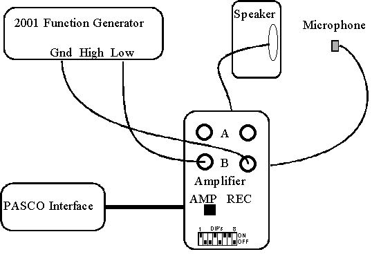
  2. Eternal function generator (use LOW output).
  3. External computer speaker.
  4. Microphone mounted vertically and amplifier in AMP setting.
  5. Yard stick.
  6. Tuning forks (two per group).

General:

  1. Remember: Frequency = 1/Period.
  2. Check notes in the PASCO notepad.


Instructions:

  1. Shake mouse to awaken the computer
  2. Enter User name: Physics and Password: Labs.
  3. Double click on the Science Workshop icon.
  4. On the File menu, click open.
  5. Choose Network, under Path choose \\NEWTON\SCIWKSHP
  6. Double click on Phys107 and double click on lab1.sws.
  7. Select oscilloscope settings to change the range on time and voltage.
  8. Use the MON option.
  9. Use the crosshairs to read values off of the oscilloscope.
  10. Part A

  11. One group will start the function generator, set it for a sine waveform, strike the tuning fork, listen and match the output frequency of the function generator to that of the fork.
  12. Using the microphone and the oscilloscope, the other group will determine the frequencies that the first group selected. Record your measurements. DO NOT consult with the first group, or look at the frequency generator (they are not very accurate, anyway).
  13. The first group will now choose a second fork and match its frequency to that of a square waveform. Once the frequency is set, go back to the sine wave before the second group measures the frequency.
  14. Now switch the roles of the two groups and repeat 10), 11), and 12).
  15. Finally, exchange your selected and recorded data.
  16. Part B

  17. Now work together. Select a sine waveform at the frequency which gives the largest amplitude (about 2000 - 4000 Hz). Don't use too large a signal, the signal should not flatten out. Adjust the time axis to see 5-10 oscillations.
  18. Place the microphone at various distances from 5 cm to 75 cm away from the speaker. Measure the distance from where you think the actual speaker is in its box.
  19. Record the amplitude of the microphone signal as a function of distance.
  20. Loudness is actually the square of the amplitude. Calculate the loudness and finish the fourth and fifth columns in the table.

Part A

Selected parameters:


Fork Number

Waveform

Recorded Frequency

Actual Frequency

Ratio

1


2


3


4


Part B

Sound amplitude versus distance:


Distance (cm)

Amplitude (Volt)

Loudness

(Volt2)

Loudness*Distance

(Volts2-cm)

Loudness*Distance2 (Volts2-cm2)

1


2


3


4


5


6


7


8


9


10


Questions:

Part A

  1. Were all of your frequencies accurate for the sine waveform? Square waveform?
  2.  


  3. If not, by what multiplicative factor were they off? Write this as a ratio of simple integers.
  4.  


  5. Do these ratios correspond to intervals that you know?


Part B

  1. Which column (4 or 5) varies less? (Find the ratio of the highest value to the lowest value). From this, how does loudness depend on distance?